PulsePoint
For Itron Domestic Gas Meters
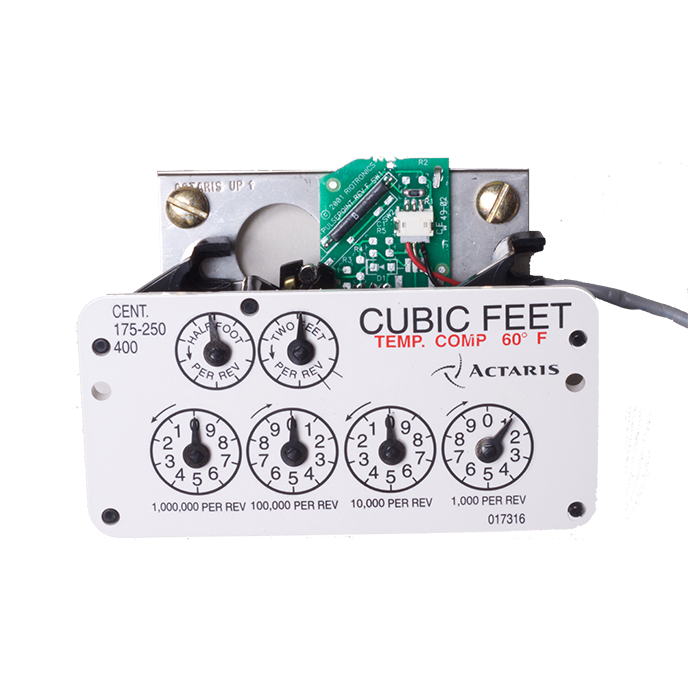
For Itron/Actaris/Sprague residential and Metris gas meters. Ideal for both AMI and submetering applications. Fitting 240-250-400 cfh sizes, this device can be shop or field retrofitted to both direct read and circular read index meters, and is concealed behind the meter index, with only a cable showing. 2/rev drive dial resolution having 1 cu’/pulse, with digital Form A or transistor-power saving outputs are available. Approved by Canadian authorities.
Output: Form A, Digital dry contact; optional “PS4” FET transistor output for power saving
Resolution: 1 or 2 pulses/rev of drive dial
Maximum Pulse Rate: Based on meter speed; approx 3 seconds/pulse shortest output with 2/rev on drive dial
Duty Cycle: 40% on, 60% off, ± 6%
Temperature: Operational from -40° to +240°F
Options for All Products: dual, separate outputs; FET type electronics; custom wire lead lengths; wire tamper sense
These instructions describe field or shop installation for RIO Tronics Corp PulsePoint gas meter sensors, designed for fast, reliable pulse unit installations onto domestic gas meters from American/Canadian meter, Invensys/Rockwell, and Schlumberger/Sprague.
Instructions also available as PDF.
Meter Applications:
- Elster/American/Canadian- all circular read, and direct read for Class 175-250
- Sensus/Rockwell- circular read for Class 175/250/400
- Itron/Actaris/Sprague- circular read and direct read for Class 175/250/400
1) Remove Index Cover
2) Remove Index
3) Snap on Magnet Assembly
American and Invensys Indexes use the same flat type magnet assembly, which snaps onto the drive shaft of the index. The Schlumberger magnet assembly is the shaft with T type magnet carrier assembly. See the below pictures. Snap on the magnet assembly to the index drive shaft, on the back side of the index, with the retaining tabs facing the index. Rotate the drive shaft, and adjust the spring clip on the shaft to ensure that the assembly does not touch the index back through a complete revolution.

Elster/American Meter Magnet Assembly

Sensus/Rockwell

Itron/Sprague Magnet Assembly
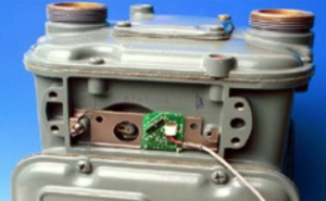
4) Position Switch Bracket onto meter between meter and index, aligning the bracket with the index screw holes
Refer to the photos below for correct bracket and alignment:
Elster/American Meter Bracket Alignment

Sensus/Rockwell Bracket Alignment
Itron/Sprague Bracket Alignment
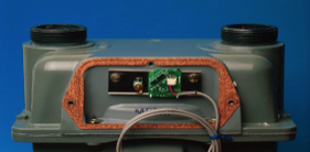
5) Secure the switch bracket between the index and the meter, and re-mount the index.
For American: use the extended index mount screws, and ensure the index drive pin aligns properly with the meter drive. View the index assembly from below to ensure alignment, and turn the test dial on the face to confirm drive pin alignment
Invensys/Rockwell: Mount as shown in photo above, using original index screws
Schlumberger/Sprague: Mount bracket with one index screw loosely secured, align the index, and secure both index screws. Ensure the proper index drive pin alignment with the meter drive.
6) Drill the index box with a 7/32” hole for the wire grommet. Use a side or bottom location on the index box for weathering.
Exit the wire through the grommet, and use a lubricant as silicone or WD40 to help the wire through the grommet.
7) Secure the index box with its original screws and gaskets.
8) To test the output from the PulsePoint:
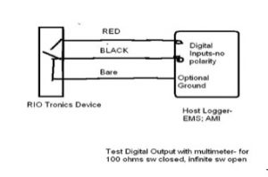
Run the meter through at least 2 cu feet of consumption, and check for pulse actuation with a multimeter- connect the red and black leads from the PulsePoint to the test leads, and confirm the change from 100 ohms to infinite for each contact closure.
9) Connect to the host recorder, data logger, AMR device: The red and black wires are the pulse output, without polarity. The bare, wire is shorted to the black wire, and may be used to monitor continuity with the black wire as a wire tamper detection option.
RIO Tronics has a distributor network across the US and Canada, and can refer them via email or phone. Please send us a message using the form below or call us at 303-733-2600 for more information.
Call to Order
303-773-2600
For additional product details, distributor, or pricing information,
please email in the section at the right, or phone at the number above.
We can also answer questions about delivery times and product features and options.
For information on availability of outputs for your meters, please send photos of the meters, with close up photos of the dial sections, via the form at the right on this page.